Memahami Standar EIA-481-D untuk Pita Pembawa
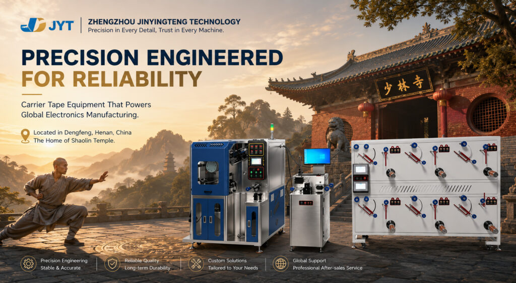
EIA-481-D is the foundational specification that makes automated electronics assembly possible. It defines the physical dimensions, tolerances, and orientation rules for embossed carrier tape used to package surface-mount components for high-speed pick-and-place equipment. Without this standard, every component manufacturer would produce tape incompatible with every placement machine. Zhengzhou Jinyingteng (Henan Jenten) designs carrier tape forming equipment built to meet and exceed EIA-481-D requirements for precision and consistency.
What EIA-481-D Covers
EIA-481-D, published by the Electronic Industries Alliance (now part of the Electronic Components Industry Association), specifies the standard for embossed carrier taping of surface-mount components for automatic handling. The standard addresses the complete tape-and-reel system: the carrier tape that holds components, the cover tape that seals them, the reel onto which the tape is wound, and the leader and trailer sections that enable machine loading.
The standard governs mechanical parameters only. It does not dictate electrical characteristics, thermal behavior, or solderability of the components themselves. Its purpose is to establish a unified mechanical interface that ensures interoperability among component manufacturers, SMT feeders, and placement equipment globally.
Key Dimensional Requirements
Sprocket Hole Pitch and Cumulative Tolerance
The drive hole pitch (Po) is standardized at 4.00 mm, defining the tape advance for each feeder indexing cycle. Drive holes have a nominal diameter of 1.50 mm with defined tolerances to ensure positive engagement with feeder drive wheels.
Cumulative tolerance is the critical parameter. EIA-481-D specifies that any ten consecutive sprocket holes must maintain a cumulative error within ±0.2 mm. This cumulative measurement, rather than individual hole tolerance, determines whether the feeder maintains positional accuracy across the tape length.
Pocket Dimensions and Component Clearance
The cavity defined by A0 (pocket width), B0 (pocket length), and T (depth) must surround the component with sufficient clearance to satisfy specific requirements:
- The component must not protrude beyond either surface of the carrier tape
- The component must be removable in a vertical direction without mechanical restriction after cover tape removal
- Component rotation within the pocket is limited to a maximum of 20°
- Lateral movement of the component is restricted to 0.5 mm maximum
The component must also pass around a bend radius of 30 mm without damage, and the tape must release from the reel hub without damaging the carrier tape or remaining components.
Tape Flatness: Camber and Bow
EIA-481-D specifies strict tolerances for tape deformation. Camber—lateral curvature in the horizontal plane—is limited to a maximum of 1 mm lateral movement across 250 mm of tape length. Excessive camber causes friction in feeder guides and misalignment of drive holes.
Bow refers to curvature in the vertical plane. While camber is more frequently cited as the critical parameter for feeder performance, both deformations can affect tape tracking and indexing reliability.
Leader and Trailer Specifications
The standard defines minimum lengths for leader and trailer sections. A leader of at least 400 mm of cover tape is required, including at least 100 mm of carrier tape with empty compartments sealed by cover tape. A trailer of at least 160 mm of empty carrier tape sealed with cover tape is also required. These sections enable machine loading without component loss.
Component Orientation Rules
EIA-481-D introduced significant changes in standardizing the orientation of Pin 1 for polarized components. The revision moved Pin 1 to specific quadrants to better align with industry practices.
The orientation varies by component type:
| Component Type | Pin 1 Quadrant |
|---|---|
| BGA, SOIC, SOP, SSOP, QFNR, DIP | Quadrant 1 (Lower Left) |
| TO-252, TO-263, QFNS, TSSOP | Quadrant 2 (Upper Left) |
| SOT and miniature parts | Quadrant 3 (Lower Right) |
| PLCC, LCC | Quadrants 1-2 (Left Center) |
This standardization ensures that pick-and-place machines pick up polarized components in a predictable position, reducing programming complexity and preventing reverse polarity defects.
The Precision Challenge: Beyond Baseline Tolerances
EIA-481-D allows pocket dimension deviations up to 100 micrometers. This tolerance is acceptable for chip passive components and larger SMD semiconductor devices. However, smaller components require tighter control—approximately 50 micrometers to prevent excessive rotation or tilt within the pocket.
The newest package types, including WLCSP and advanced BGAs, demand tolerances of 30 micrometers. These packages may also require pockets that are 44% shallower relative to larger devices. Only high-precision polycarbonate carrier tape can consistently deliver this level of dimensional control.
This precision gap explains why carrier tape forming equipment design matters. Baseline EIA-481-D compliance is a starting point, not a destination. Equipment that maintains P2 within ±0.03 mm for small-component tape, with independent servo punching decoupled from tape transport, provides the foundation for meeting the tighter tolerances that advanced packages require.
Material Implications
EIA-481-D does not mandate specific materials. In practice, polystyrene (PS) dominates standard carrier tape applications, while polycarbonate (PC) is preferred for precision semiconductor packaging. PS tapes can have relatively high camber yet still remain within EIA-481 specifications. PC offers lower shrinkage and better dimensional stability, supporting the tighter tolerances that advanced packages demand.
For ESD-sensitive components, conductive or static-dissipative formulations are commonly used. Typical surface resistivity requirements fall within the range of 10⁴ to 10⁸ ohms per square, dissipating triboelectric charge during high-speed feeding without damaging sensitive circuitry.
Engineering Partnership for EIA-481-D Compliance
EIA-481-D defines the mechanical interface that makes automated assembly possible. Meeting its requirements consistently—and exceeding them where advanced packages demand tighter tolerances—depends on the precision of the carrier tape forming equipment.
Zhengzhou Jinyingteng (Henan Jenten) manufactures carrier tape forming equipment designed for EIA-481-D compliance. Our roller-type forming systems integrate thermal forming, independent servo punching, and multi-lane reeling to produce tape with consistent sprocket hole positioning, pocket dimensions, and camber control. For manufacturers producing carrier tape for semiconductor and IC packaging, our equipment provides the foundation for dimensional consistency at production volume.
 ID
 EN_GB
 KO
 VI
 RU